Learning Unreal Engine 3 – UE3 Editor
Material Basics 2
In this section we’ll look at some more useful material techniques. We’ll learn how a few new node types work, we’ll make glowing materials, and we’ll make some blended materials.
1) Duplicating a material
The material you created in the last section is really useful, so you wouldn’t want to modify it anymore. But you also don’t need to start from scratch. You can create a duplicate of the material you just created, and use it as a starting point for this tutorial.
Close the Material Editor window if it’s still open. In the Generic Browser window, find the package you’ve been working in and select it. Select the material you created (BasicMaterial), right-click on it, and click on Duplicate.
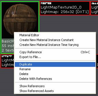
In the window that pops up, in the New Name field, name your material “GlowMaterial” and hit OK. It should show up in the package.
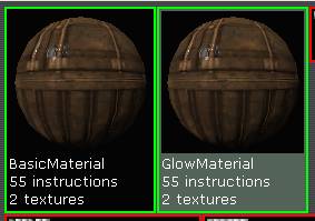
Double-click on it to open up the Material Editor.
2) Material hotkeys
Before you dive in, let’s look briefly at some hotkeys you can use in the material editor. Hotkeys for creating a node are similar to the hotkeys for placing an object in the world – hold a certain key and click, and your node is created.
For instance, you can hold the “t” key and click in the material editor to create a new texture node. There are shortcuts for most common node types – “m” for multiply, “a” for add, “d” for divide, etc. You can also hit “1” for a Constant and “3” for a Constant3Vector. It’s a big time-saver, so I recommend using hotkeys wherever possible.
Also, if you ever need to disconnect a node, you can alt-click on the connection to disconnect it.
3) Glowing Materials
We’ve seen already that anything that gets plugged into the “Diffuse” channel gets displayed on an object’s surface. And it receives lighting, so if it’s in shadow, it’ll appear black. We need a way to make our texture glow. Anything attached to the “Emissive” input will glow regardless of lighting, so let’s plug something in.
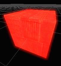
Create a new Constant3Vector and give it a value of 1,0,0, which is red. Attach it to the Emissive input. (You may want to move some of the other nodes aside to make some room.)
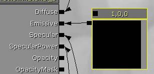
The material preview now glows bright red. You can still see the diffuse texture and specular highlight poking through, but the red color takes over.
Try plugging in a brighter value (say, 5.) You’ll notice that not only is the preview bright solid red, it has a slight bloom surrounding it. This is a handy trick – any time a surface color goes above “1”, the surface glows.
But glowing solid red isn’t very useful. Let’s replace that Constant3Vector with a texture so that we can get an interesting pattern.
Look in the HU_Deco package and find the texture named T_HU_Deco_SM_CitySign01b_E. Select it.
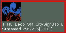
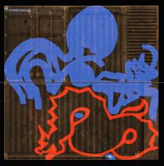
Delete the red Constant3Vector, create a TextureSample node, and plug it into the Emissive channel. You’ll see the pattern applied to the material surface.
Hit the check mark to apply changes, and assign the material to a surface in your level. You may want to move your light or decrease its radius if the glowing effect isn’t obvious.
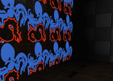
Now, this may not seem particularly useful on a tiling surface like a wall, but if you look in the HU_Deco package, you’ll see plenty of static meshes that have a glowing material on them.
4) Controlling texture tiling
So what if we wanted the glowing part of the texture to tile over a larger area, but we wanted to leave the diffuse texture alone? We can control the UV tiling of a texture using a TextureCoordinate node.
Create a new TextureCoordinate node, and plug it into the “UVs” input of your emissive Texture Sample.
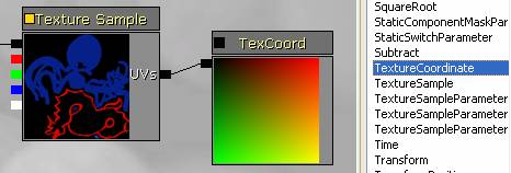
You won’t notice any change right away, but if you select the TexCoord node, you’ll see two properties at the bottom of the window – UTiling and VTiling.
![]()
By changing these numbers, you can change how frequently the texture tiles. Larger numbers mean the texture tiles more often, and smaller numbers mean it tiles less often (in other words, it’s stretched over a larger area.)
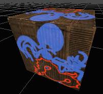
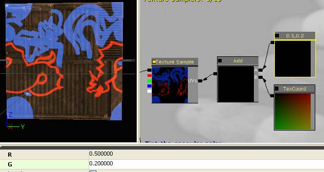
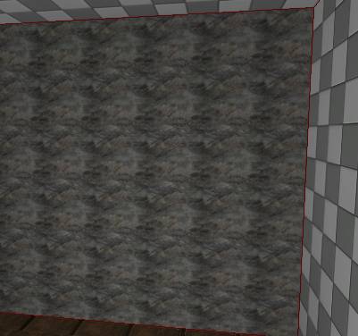
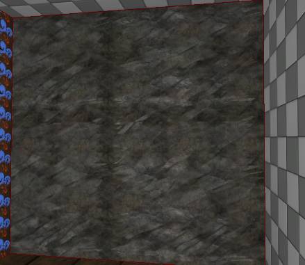
Set the tiling to 0.5, 0.5, apply the changes, and look at the results in your level.
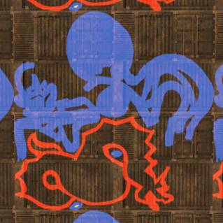
You can see that while the base texture tiles twice, the emissive texture only tiles once.
5) UV Offset
You can do a lot more with that UV input than just control tiling. Let’s look at some other tricks.
To keep things simple, change the tiling values on the TexCoord node back to 1.0, 1.0.
First, let’s look at how to offset the glowing texture up and to the side. You may have noticed that there aren’t any options for offset in the properties, so we’re going to have to use an Add node to add in an offset. We’re also going to use a new Constant node type – a Constant2Vector. After all, texture coordinates are in UV space, which is just a set of two values.
So create an Add node, create a Constant2Vector, and hook them up like this:
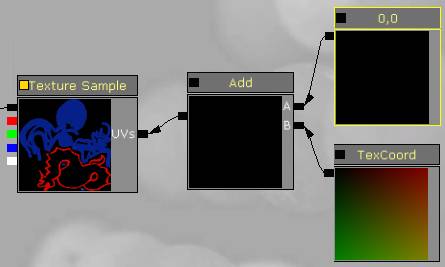
No difference, right? That’s because our Constant2Vector has values of 0,0, so we’re not adding anything in.
Try changing the numbers. Anything between 0-1 will work. (If you add a whole number you won’t see any change, because it tiles an even number of times.) The properties say R and G, but you can think of that as any dimensions you want – RG, UV, XY, whatever. I plugged in 0.5 and 0.2, so it moved it horizontally half way, and up slightly.
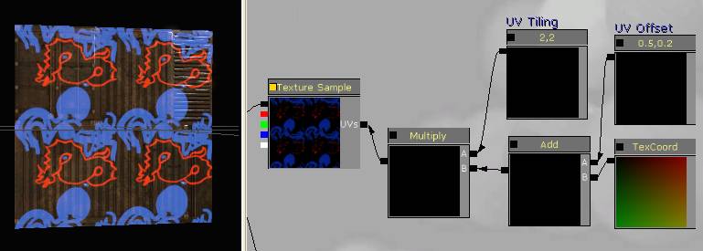
We saw earlier that you can change the tiling in the TexCoord node, but you can also change it by adding a Multiply to node network. Create a new multiply node and a Constant2Vector, hook them up as follows, and give the Constant a value of 2,2.
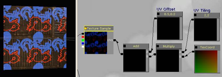
It’s exactly the same result as you would get by changing the values in the TexCoord node. BUT! Multiply and Add are order dependent. If you switch it around so that the Add happens first, you get a different result.
It may help to think of this in math terms. In the first example we’re doing the multiply first, so we have (X*2)+0.5. In the second we’re adding first, so we have (X+0.5)*2. Big difference – in the second version we’re adding 0.5, but then multiplying that by 2, so in effect we’re adding 1. In the first version we do the add at the end, so we’re just adding 0.5 unmodified.
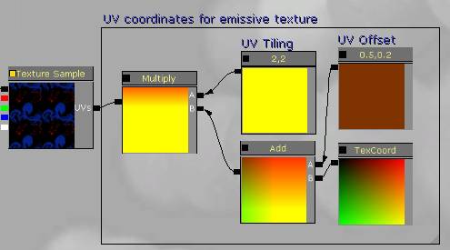
So now you’ve seen the basics of how UVs work. The TexCoord node reads the UV coordinate for a given point on the mesh. If you Add a Constant2Vector to it, it offsets it. If you Multiply it, it scales the coordinate, which has the effect of changing the tiling. You can actually do anything you want to the coordinates, and with some tricky functions, you can get effects like scrolling textures, rippling water, reflections, multi-layered effects that change with camera angle, and a ton of other cool stuff. We’ll look at those in another tutorial though.
For now, add some useful comments to your network, apply any changes, and save your work. Next we’ll look at some practical applications of texture tiling.
6) Blended materials
A common problem in video games is the effect of textures repeating across a surface. In older game engines, the solution was usually to cover up the repeating elements with decals or meshes, and to paint textures where the repeating detail isn’t very obvious.
In Unreal, we can create a blend that helps hide repeating surfaces.
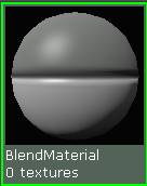
Let’s do this in a new material. Create a new material, and name it BlendMaterial. Double-click it to open the Material Editor.
Switch back to the Generic Browser and select the UN_Cave package. Fully load it.
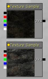
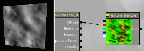
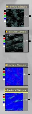
There are two textures we’re going to use for our blend – T_UN_Cave_Dirt_Floor_D, and T_UN_Cave_Rock_Floor_D. Create texture samples for these now, and lay them out so that the dirt texture is on top and the rock texture is on the bottom.
Connect the dirt material to the Diffuse channel, apply the changes, and assign the material to one of the walls in your scene. The tiling artifacts are definitely showing.
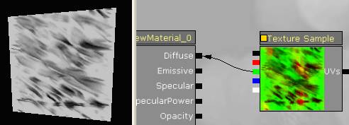
The first thing we need to do to blend between our texture samples is to pick a good mask texture. In the UN_Cave package, there’s a texture created exactly for this purpose, named T_UN_Cave_Dirt_Floor_Masks. Create a texture sample for it now.
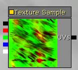
It looks kind of like a modern art painting, but that’s because the different color channels are meant to be used separately, and Epic wanted to save texture memory by putting them into the same texture. There are actually two masks in this texture – one in the red channel, and one in the green. To get a sense for what they look like, connect the red texture output to the Diffuse channel, and then try the green. The difference is much clearer when you view them separately.
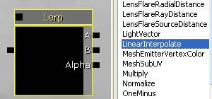
7) Linear Interpolate
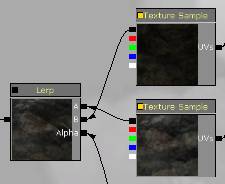
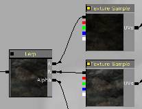
To perform the blend between the textures, we need to use a new node type – LinearInterpolate, or Lerp for short. Create one now.
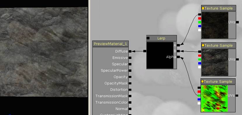
Notice it has three inputs – A, B, and Alpha. We can plug textures into A and B, and one of the color channels from our mask into Alpha, and the Lerp node will perform the blend for us. Hook this up now (using the green channel from the mask), and attach the output of the Lerp node to your diffuse channel.
If you don’t quite see what’s happening, try comparing the output of the Lerp node with the output of your texture samples. (Temporarily connect one of the textures to the diffuse channel and look at the difference.)
Apply the changes to your material and check it out in the scene. Uh-oh, that actually looks worse than before!
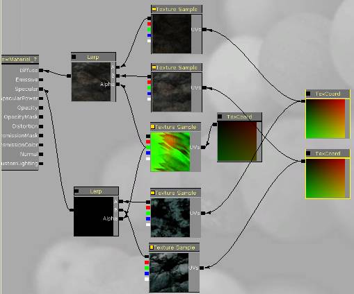
That’s fine, we can fix it by playing with the texture tiling. Create three Texture Coordinate nodes and attach them to your textures.
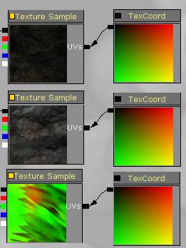
What we want to do is pick numbers that aren’t multiples of each other, so that repeating elements of the textures don’t line up. For the texture samples I picked 0.8 and 0.7, and for the mask, 0.3. This was a little trial and error, but from a math standpoint, this works out pretty well too. The textures have a slight offset from each other so that they don’t overlap very often, and the mask is scaled much larger since we don’t care as much about the texture detail.
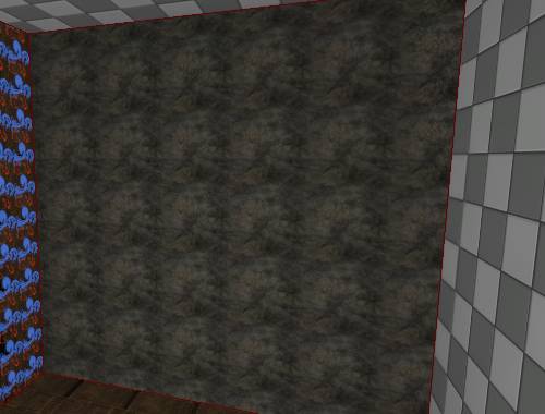
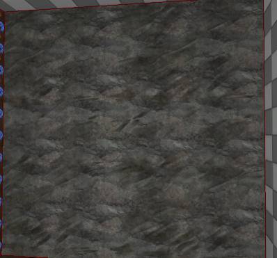
Apply the changes and look at the result in your scene.
You can still pick out elements that repeat, but they’re not nearly as prominent as before, and they don’t repeat as regularly.
You can also swap the inputs to A and B to invert which texture shows where.
Switch your material back to normal, apply changes, save your work, and we’ll look at how to get this working with normal maps and specular maps.
<
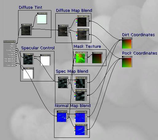
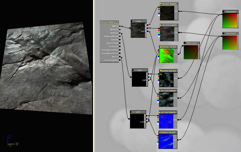
8) Blending with normal maps and specular maps
Let’s get this material up to par with what we’ve built in the past. Normal maps will add a ton of detail to the rock walls. There are also some really good specular maps painted for these textures, so we’ll use those instead of tinting the diffuse map like we did before.
First things first, create texture sample nodes for the normal maps and spec – you’ll find the textures in the same package as the Diffuse textures, and it’s sorted alphabetically so they’ll all be near each other. (Import T_UN_Cave_Dirt_Floor_S, T_UN_Cave_Dirt_Floor_N, T_UN_Cave_Rock_Floor_S, T_UN_Cave_Rock_Floor_N.)
Arrange the Texture Sample nodes so that the spec maps are together and the normal maps are together, and so that the dirt and rock textures are in the same order as above (dirt on top, rock on the bottom.)
Now create a new Lerp node. Hook up the spec maps just like you did with the diffuse textures. Reuse the green channel from the mask. Then pipe the Lerp node into the Specular channel. And most importantly, pipe the TextureCoordinate nodes from the diffuse textures into their matching specular textures – this will ensure that they tile with the same frequency.
Now do the same thing for the normal maps. You’ll see a big difference in the way the material looks now.
At this point, add any of the other standard controls you need – a multiplier for the Specular, a constant for the SpecularPower, and if you want, a tint for the Diffuse.
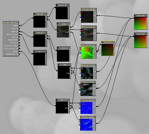
Last step – comment everything, and be sure to save your work.